Manley and his ventilator
This is a nerdy history deep-dive into a really cool piece of kit that transformed anaesthesia for ever.
If you're in the midst of a caffeine-fueled last-minute revision panic, my advice is to speedily move on to another more high-yield topic that is actually likely to win you some marks on exam day.
The chances of this topic coming up in a meaningful way is minimal, so please don't stress about needing to know this information in detail.
Just tell me the facts I need to know for the exam.
But of course.
The Manley MP3 ventilator is a pneumatic, time-cycled, minute volume divider.
- It has three one-way valves
- Two sets of bellows
- It acts as a Mapleson D breathing system during spontaneous ventilation
The advantages are:
- No power supply needed
- Robust and simple
- Reliable
The disadvantages are:
- It only has a single ventilation mode
- It will generate back pressure to the back bar as it cycles
- It's not great for non-compliant lungs
- You can't use the O2 flush while it's working
The aim of today's post is to explain precisely what this actually means and why.
If on the other hand, like us, you're an unapologetic supernerd who just enjoys understanding how our kit works, and how the geniuses who devised these impressive machines figured them out, then please join us as we delve into the inner workings of a beautifully elegant piece of equipment.
Why should I care about this?
Because it's SO COOL.
It's one thing to program a computer attached to a load of servos and switches to deliver ventilation to a patient.
It's on a whole other level to make a mechanical contraption that does it automatically, with adjustable targets, built in safety features and no electricity whatsoever.
The sheer depth of understanding of physiology, physics and engineering demonstrated by Manley when he built this thing is absolutely incredible, and he did it all as a senior house officer in the 1960s.
The Manley ventilator
We owe a great deal to the legendary Roger Manley for his development of what was essentially the first reliable automatic ventilator in 1961.
Prior to this, anaesthetists (or their medical students) would generally hand ventilate their patients should they be so inconsiderate as to stop breathing during their anaesthetic, and they would do so for the entire case if required.
There had been a flurry of interest in the development of electronic ventilators, but until this point - courtesy of widespread ether usage - there had been rather too many sparks and explosions to call them anything resembling 'reliable' or 'safe'.
To give you an idea of just how keen this Manley chap was, having attended a symposium on the management of ventilatory failure in 1959 as an SHO, he then went home and produced his first working prototype in just two days.
After fiddling around in his garage with some old bits of kit and one of John Blease's patented electronic 'pulmoflators', he eventually came up with the simply genius invention that is the Manley pneumatic ventilator.
What is a ventilator?
- A device capable of producing intermittent positive pressure ventilation
- That means, a tool that can push air into the patient, and let it back out again
That's it really.
So technically an ambubag attached to a medical student is a ventilator.
So how does it work?
As always here at Anaestheasier, we do our best to properly understand something rather than just memorising soon-to-be-forgotten factoids for the exams, so we'll start with the problem to be solved and work backwards.
Buckle up.
We need to push gas into our patient's lungs.
So the logical place to start is with some sort of bag, balloon or bellows.
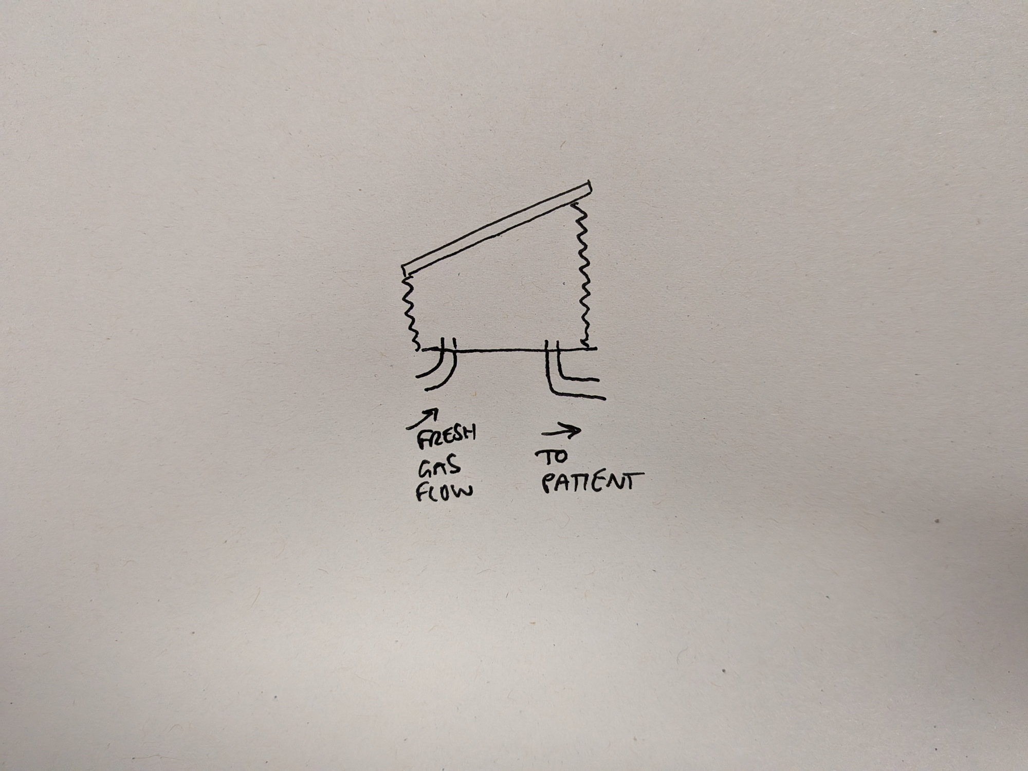
Remember we're not using any electricity here, so the next question is 'how do we squeeze the bellows?'
We put a weight on it.
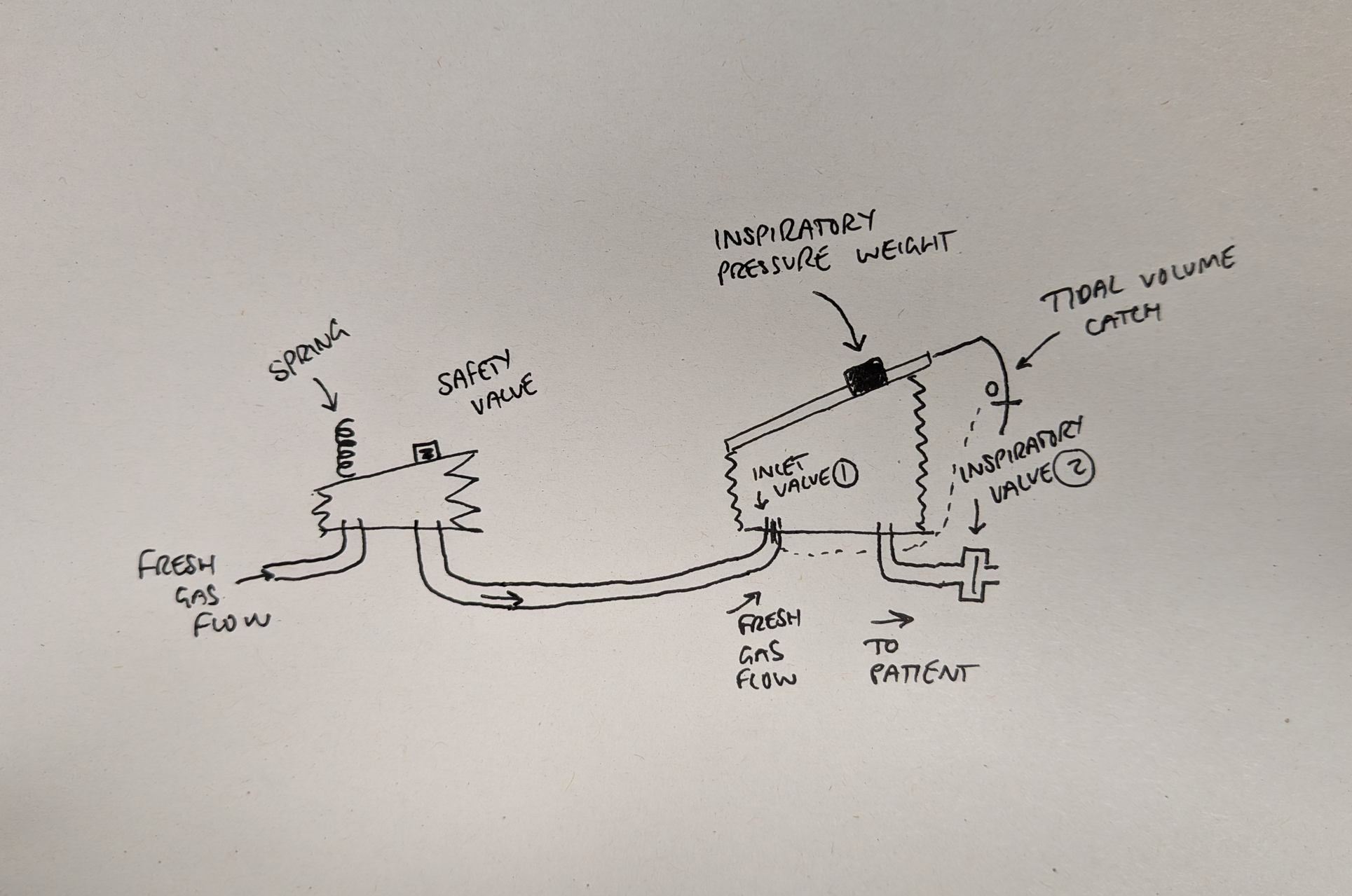
Even better, let's put a slidey weight on it that allows us to adjust how hard it pushes the top of the bellows down.
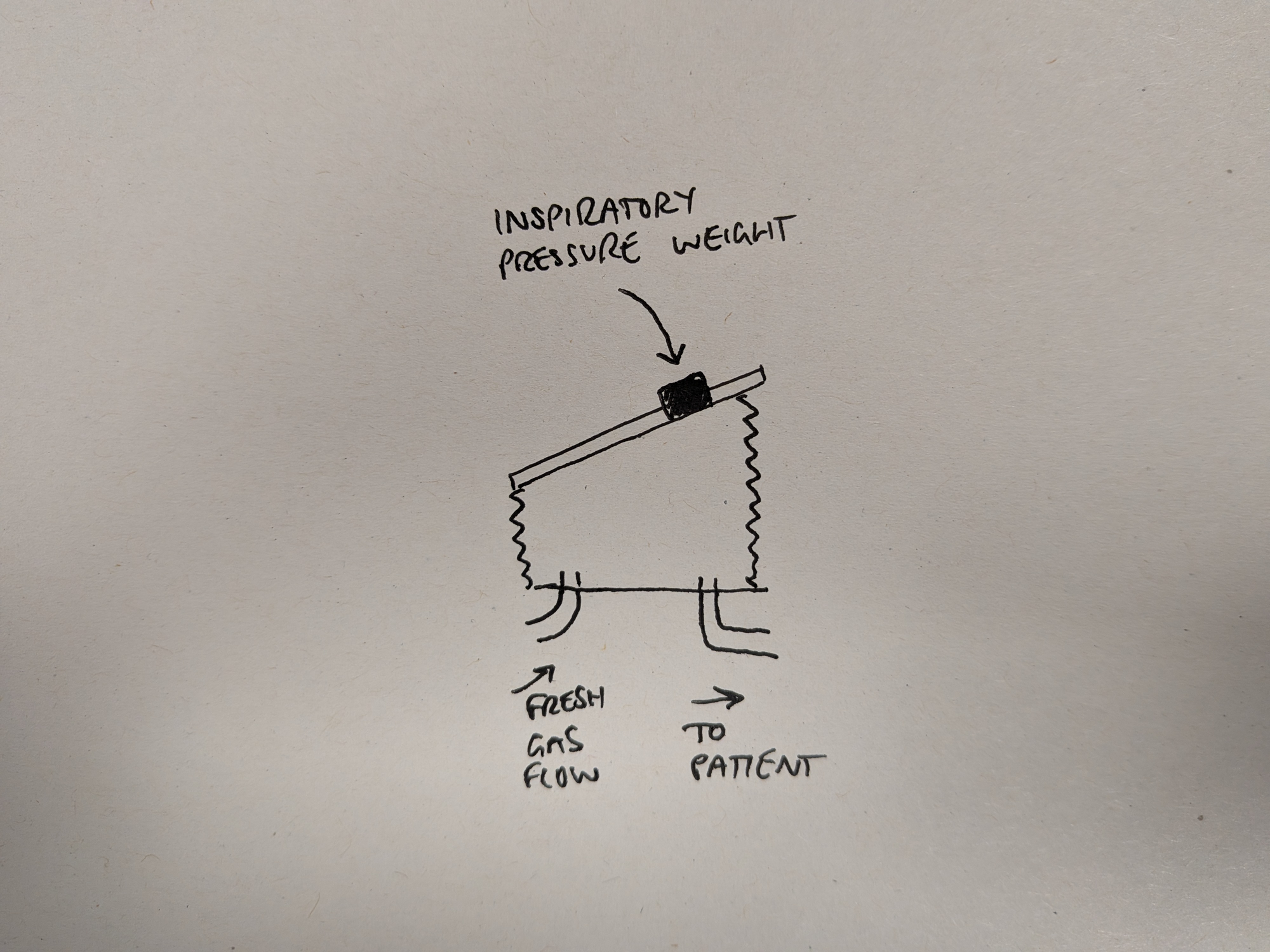
By sliding the weight along the top of the bellows, either closer to or further from the pivot point, we can generate between 8 and 30 cmH2O of pressure inside the bellows.
Adjustable inspiratory pressure.
Genius.
Now we need a couple of valves that mean the fresh gas supply to the bellows is paused while we inflate our patient (1), and the patient doesn't receive any more gas during expiration while we fill the bellows back up again (2).
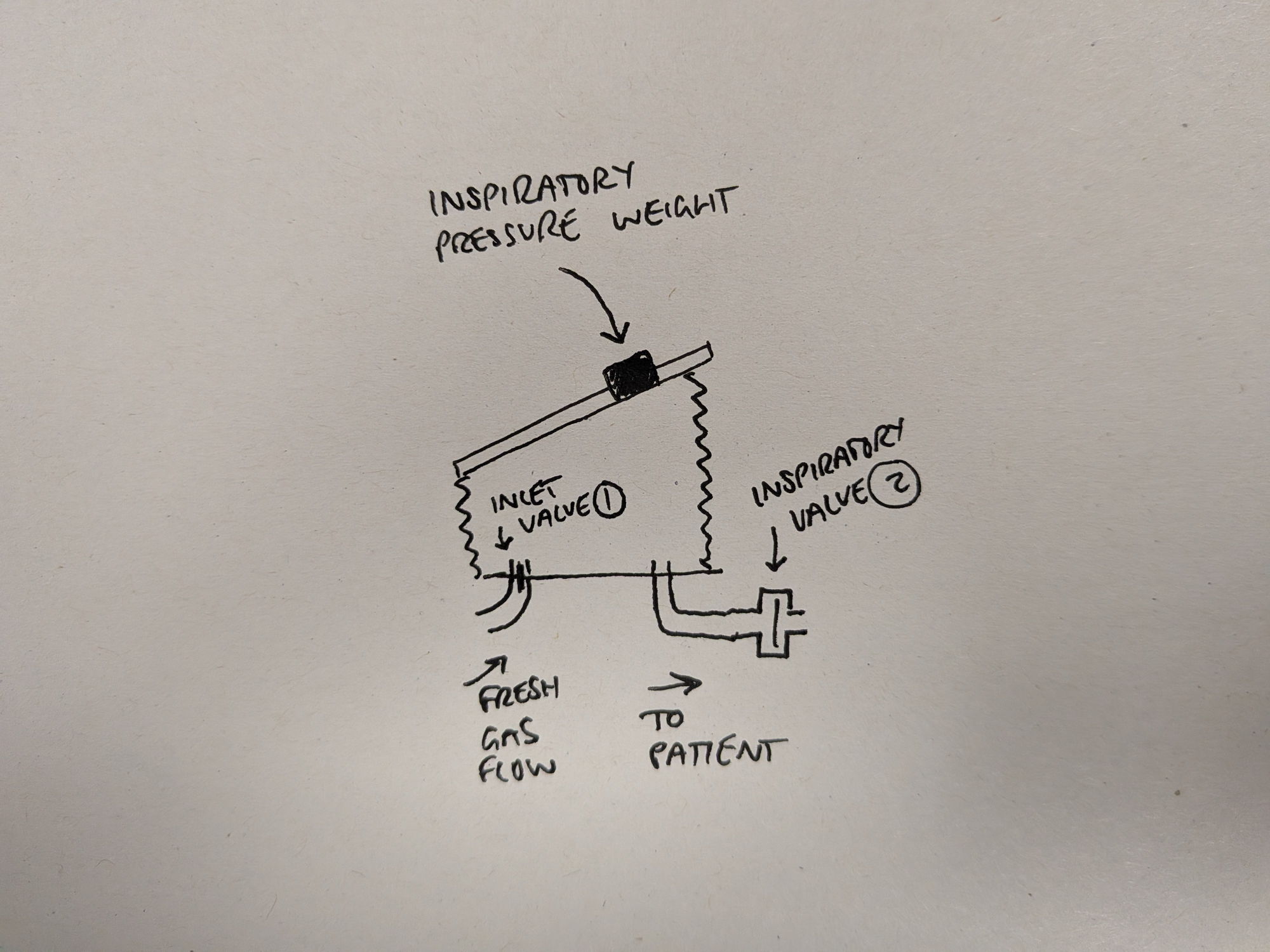
So the fresh gas fills the bellows back up during expiration, and the weight squeezes the bellows during inspiration.
Great.
Now for the next issue.
We need to control how much gas is given per breath.
How do we inflate the bellows to just the right volume before we let the weight squish it into our patient's chest?
Some sort of adjustable catch sounds sensible right?
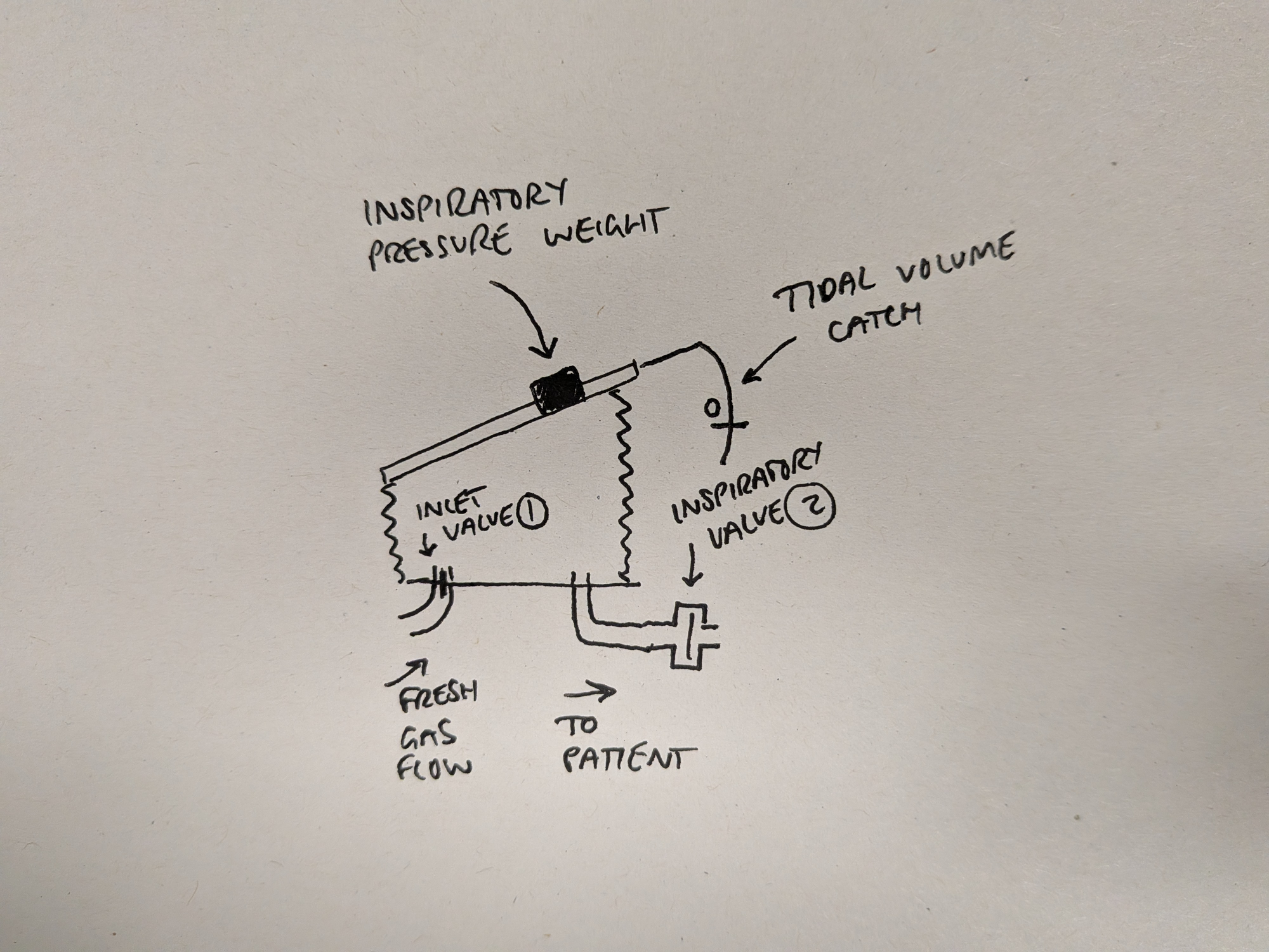
This curvy rod is attached to the top of the bellows and rises with it as the bellows inflate. There is an adjustable slider on the rod that will hit the catch at the desired set point, and stop the bellows from inflating any further.
Adjustable tidal volume - noice.
However there's still an issue - the fresh gas flow is at much higher pressure (around 300 cmH2O) than the weight can generate (30 cmH2O).
So how do we get the inlet valve (1) to close once the bellows have filled?
We need to close the inlet valve.
So we need a way of closing the inlet valve, stopping the fresh gas flowing into the bellows, and allowing the weight to deliver the neatly chosen tidal volume to the patient at a nice, safe pressure.
The answer? Let's connect that tidal volume catch to the inlet valve.
So now when the bellows reach the target tidal volume, the catch is triggered and the inlet valve is yanked shut.
This is a literal mechanical connection with strings, pulleys and sellotape (maybe not) that pulls the inlet valve shut at the correct time.
We've represented that complex mechanical linkage here with a very complicated dotted line.
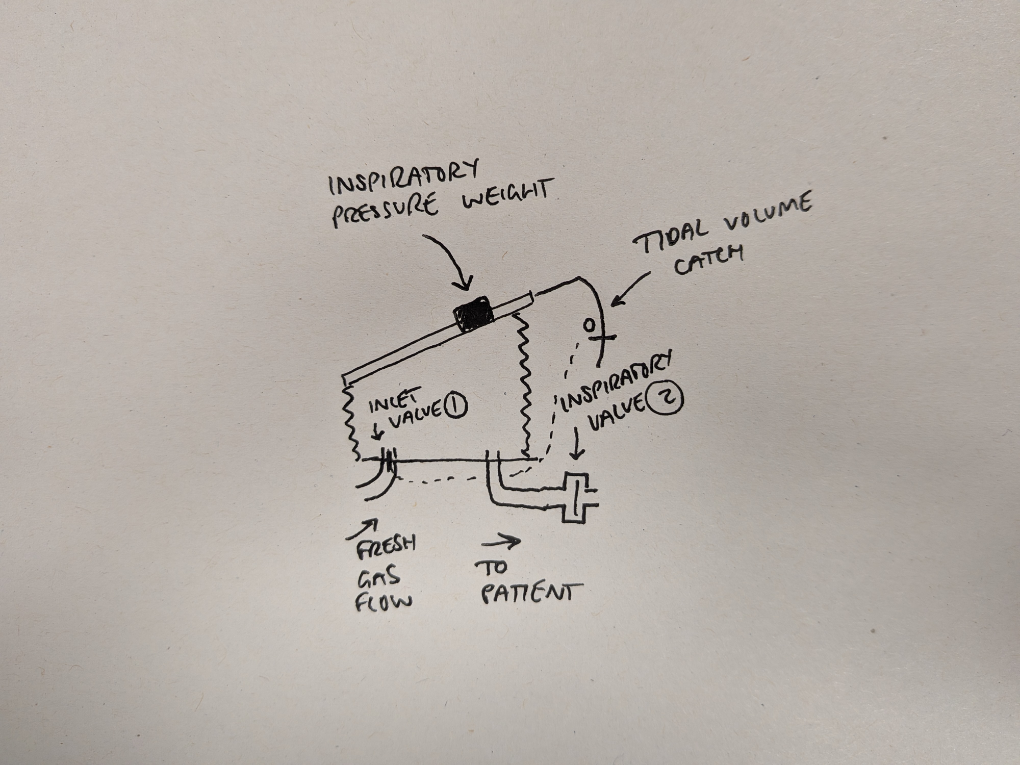
Awesome, so we have bellows that will fill to a set tidal volume, close off the inlet valve, and then a weight can squeeze that tidal volume into the patient's lungs.
Sweet.
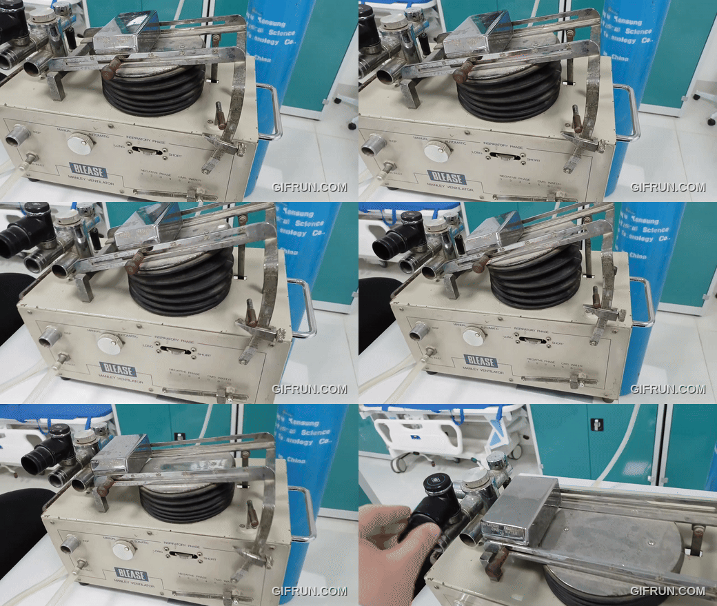
Here you can see the tidal volume catch triggering the start of inspiration. (The weight isn't supposed to slide like that however).
We need to let pressure build up in the breathing tubing
Ah yes.
If the expiratory limb of the breathing system is just open to the air, then the entire tidal volume will immediately escape into the atmosphere, rather than inflating the patient's chest.
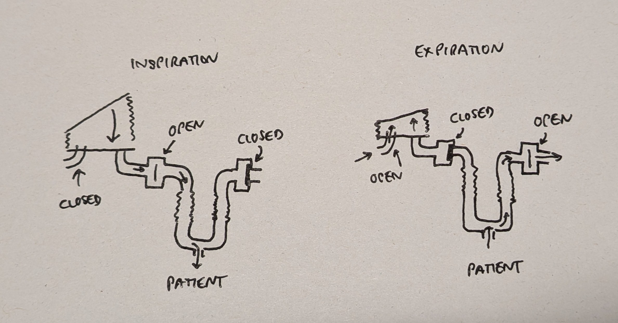
So we need an expiratory valve that will be closed during inspiration (to maintain the inspiratory pressure) and then open to allow passive expiration to occur.
So let's chuck in an expiratory limb with an expiratory valve (3) and a reservoir bag for completeness.
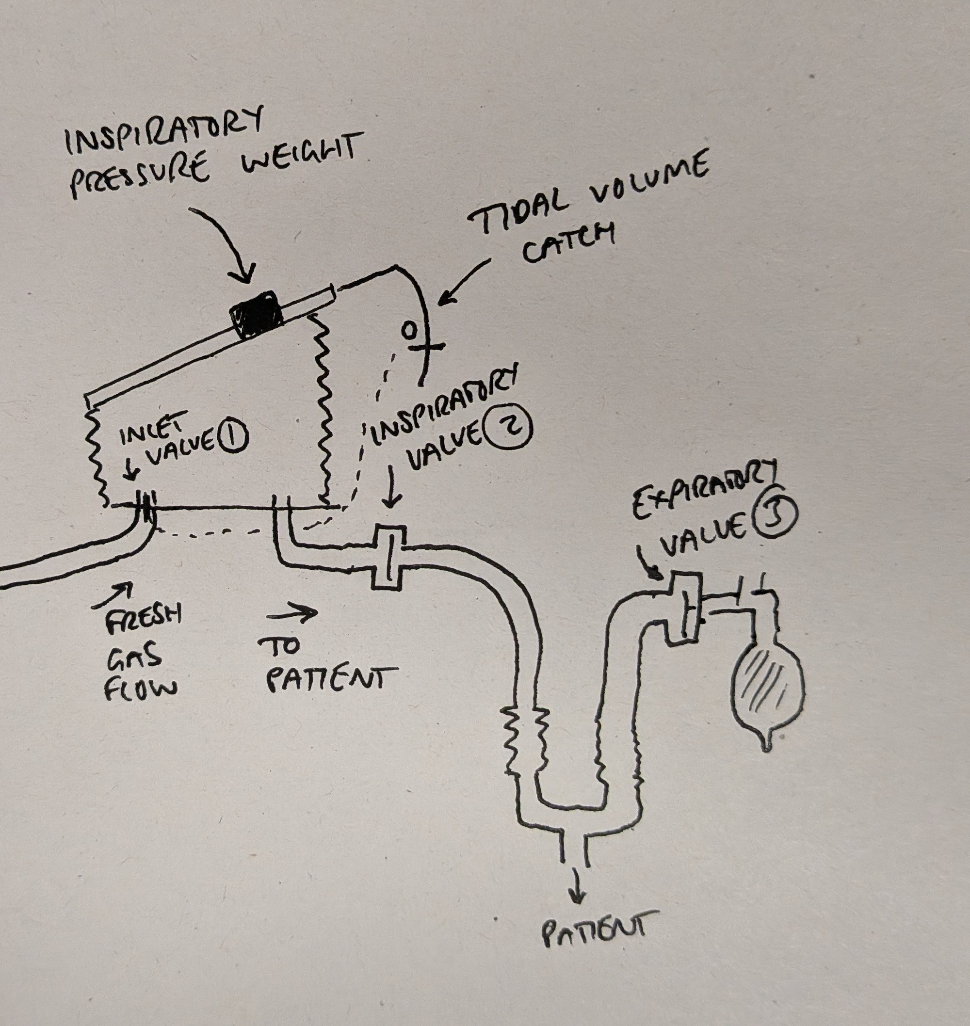
So the two phases of inspiration and expiration should look something like this:
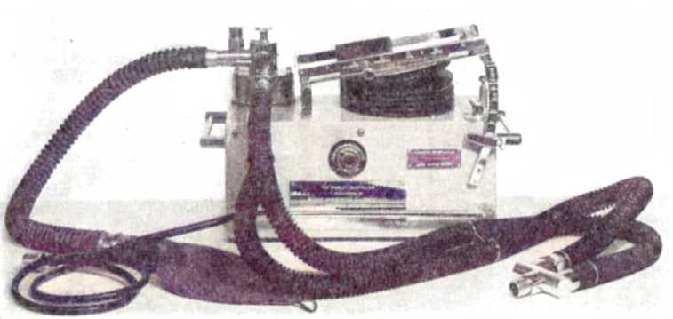
In the image (from Manley's original paper) below you can see the bellows with the slidey black weight on top and the tidal volume catch arching down the right hand side. You can also see the black reservoir bag and breathing tubing attached to the top left.
But we're not quite there yet.
There's still another issue to solve.
The fresh gas flow is constant, but the ventilation is intermittent.
It's all well and good saying 'shut the inlet valve' but that enormously high-pressure fresh gas flow isn't just going to patiently sit behind the valve while we deliver our tidal volume to the patient.
So what we need is some way of capturing the ongoing fresh gas flow during inspiration, and then delivering it to the bellows during expiration, a bit like a capacitor in an electrical circuit.
This is where the second set of bellows comes in, whose sole purpose is to convert the unrelenting constant fresh gas flow into convenient intermittent gas packages to the main bellows.
These bellows are called the time-cycling bellows and we'll get to why in a minute.
For now let's briefly recap on what we've assembled, and what it does.
Currently the sequence of events looks like this:
Let's start with the main bellows full of fresh gas, and the tidal volume catch has just forced the inlet valve (1) shut.
During inspiration
- The weight squashes the main bellows and delivers the inspiratory breath to the patient through an open inspiratory valve (2)
- The closed expiratory valve (3) ensures the gas goes into the patient, and not out into the atmosphere
- The inlet valve (1) is closed and so the fresh gas flow builds up in the time-cycling bellows instead
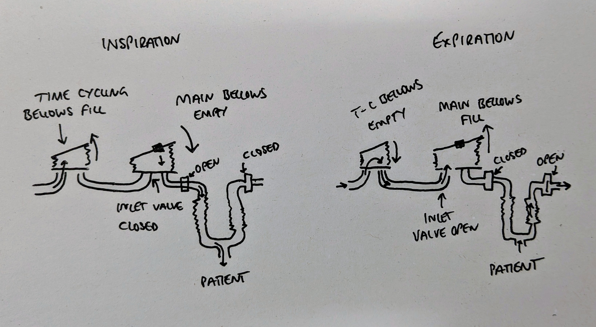
During expiration
- The inlet valve (1) opens
- The inspiratory valve (2) closes
- The expiratory valve (3) opens
- The patient exhales
- The time-cycling bellows squeeze the collected fresh gas into the main bellows
- The ongoing fresh gas flow can pass through the time-cycling bellows as well, as there are no valves here
Then the cycle starts again.
Okay...
The big switch
This is all well and good and terribly clever, but what happens when the main bellows have finished delivering the breath to the patient and sit collapsed and empty?
How does the ventilator 'know' to switch from inspiration to expiration?
This is where the 'time-cycling' aspect that we mentioned earlier comes into play.
We're going to introduce another trip lever - much like our trusty tidal volume catch - but this time attached to the second set of (time-cycled) bellows.
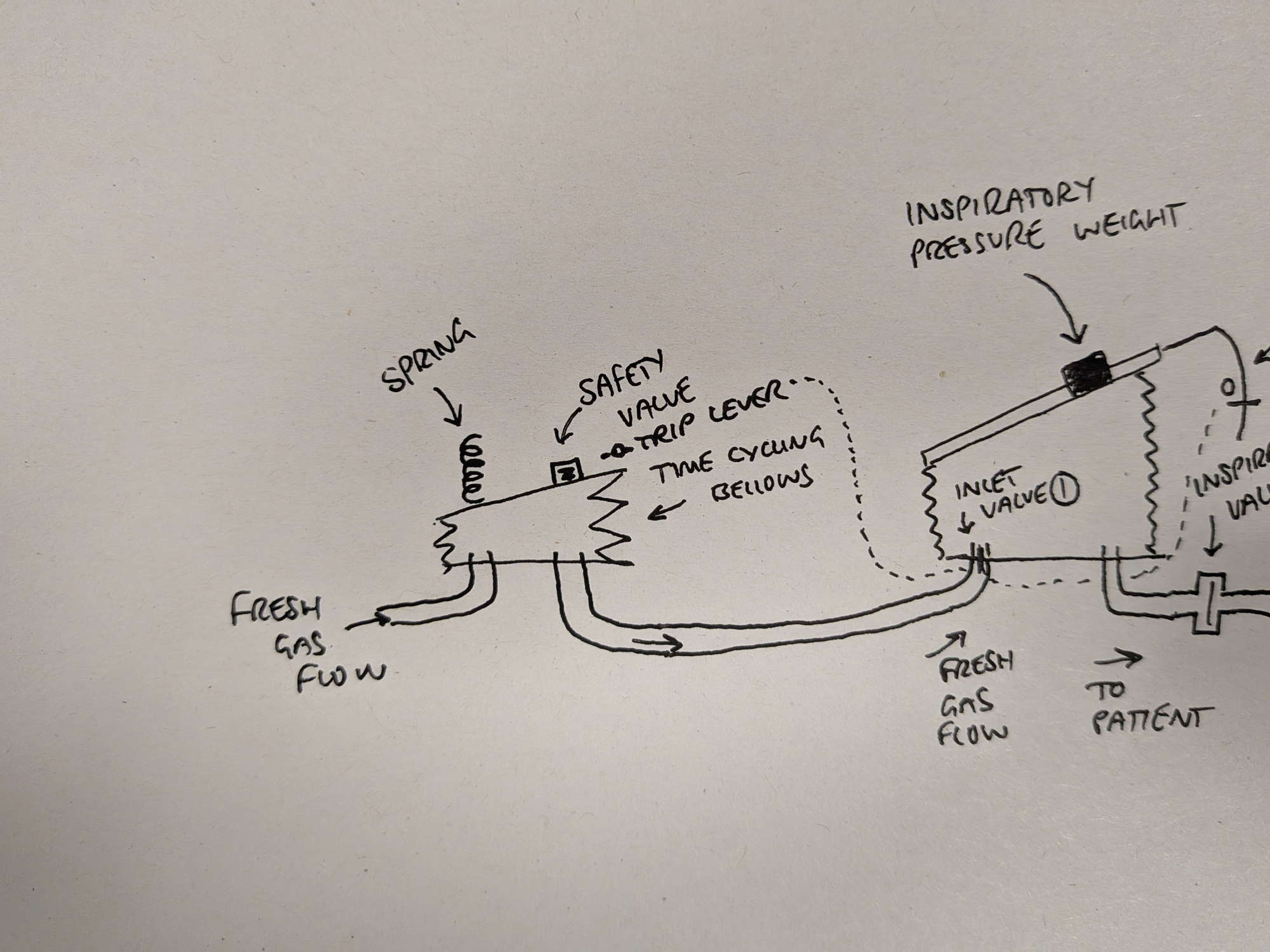
Now when the time-cycling bellows inflate, the top of the bellows eventually makes contact with our shiny new trip lever, which is also mechanically connected to the inlet valve (1), much like our tidal volume catch.
So this time, when the time-cycled bellows have reached a certain volume, the inlet valve is pulled open.
The switch from inspiration to expiration is determined by the time-cycling bellows reaching a certain volume.
Since the fresh gas flow is constant, this should take the same amount of time on every breath.
Hence they're 'time-cycling'.
So the main bellows decide when to start giving the breath to the patient (by tripping the tidal volume catch) and the time-cycling bellows decide when to stop the inhalation and start expiration.
Neat.
You as the operator can then adjust when this time-cycling switch occurs, using the big twisty dial on the front.
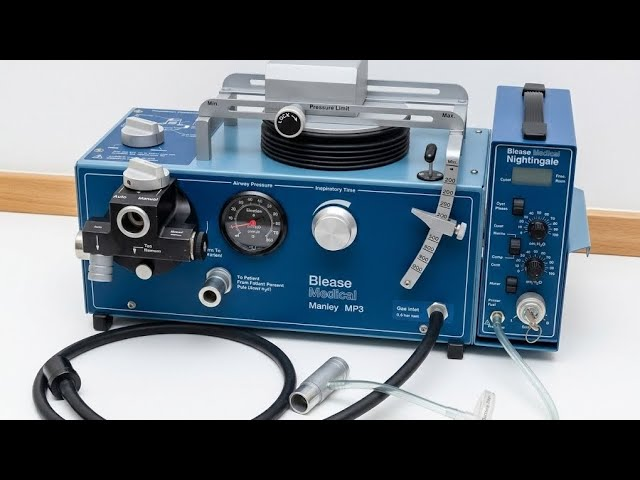
This dial allows you to control how long the machine spends in the inspiratory phase by moving that trip lever up or down.
This is very helpful, because that weight sat on top of the bellows is going to need more time to inflate less compliant lungs, and vice versa, so having some method of adjusting the inspiratory time to compensate for resistance is ideal.
We're very nearly there now.
But how do the inspiratory and expiratory valves know when to open and close?
By using some clever spring-loaded valves, and some pneumatic tubing, and zero electricity.
The inspiratory and expiratory valves are rigged up in such away that:
- The inspiratory valve (2) wants to sit in the closed position, and
- The expiratory valve (3) wants to sit in the open position,
courtesy of a couple of springs.
They are each then attached to a little diaphragm, such that pressure on the diaphragm forces the valve to move.
This diaphragm is then connected all the way back to our time-cycling bellows, via a little tube.
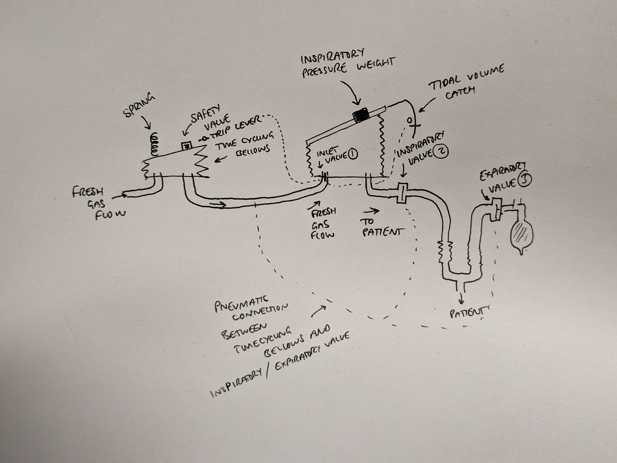
During the inspiratory phase, when the inlet valve (1) is closed, the time-cycling bellows fill with fresh gas and the pressure inside starts to rise.
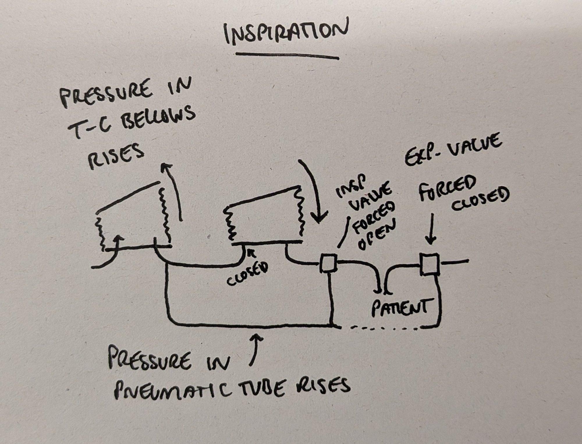
These diaphragm-biased valves are configured such that:
- The expiratory valve (3) will close when the pneumatic tube reaches a pressure of 50 cmH2O
- The inspiratory valve (2) will open when it reaches a pressure of 75 cmH2O
This is how the valves 'know' when to open and close in time with the bellows, because the bellows are mechanically controlling them entirely with changes in air pressure and some springs.

Let's bring it all together
So now let's follow the cycle through slowly, starting at end-expiration when the main bellows have just filled up.
- The inlet valve (1) is closed, and pressure starts to build in the time-cycling bellows
- The pressure reaches 50 cmH2O, causing the expiratory valve (3) to close
- The pressure continues to rise and reaches 75 cmH2O, opening the inspiratory valve, allowing the main bellows to deliver the breath to the patient (the inspiratory phase begins)
- The time-cycling bellows expand further, hit the trip lever that opens the inlet valve (1)
- The pressure inside the main bellows is only 8-30 cmH2O
- The fresh gas therefore rushes into the main bellows, and the pressure in the time-cycling bellows drops
- First it drops below 75 cmH2O, and the spring on the inspiratory valve (2) pushes the valve closed (the inspiratory phase ends)
- Then it drops below 50 cmH2O, and the spring on the expiratory valve (3) pushes the valve open, allowing expiration to begin
- The patient exhales passively as the main bellows fill
- The main bellows continue to fill until the preset tidal volume is met
- The tidal volume catch is triggered, and the inlet valve (1) closes
And that's the whole cycle.
Beautiful.
But this does beg a further question...
How do we control respiratory rate?
This machine will automatically deliver whatever fresh gas flow it is given, neatly packaged into separate breaths, straight into the patient.
The total flow entering the machine (in litres per minute) is the same as that leaving the machine into the patient's lungs, so by definition this is the minute ventilation.
The only thing it is actually doing is chunking the fresh gas flow up into intermittent breaths of a chosen volume.
This is why it is called a minute volume divider.
The faster the flow, the faster it will do this.
The overall minute ventilation is entirely dependent on how fast the fresh gas is flowing into the machine.
So if the fresh gas flow is 15 litres per minute and the tidal volume set to 500 ml, the machine will automatically chuff along like a steam train at a rather sporting thirty breaths per minute.
To slow the resp rate down, you have to slow the fresh gas flow, so we need some sort of rotameter to control the fresh gas flow entering the ventilator.
Well the easiest solution to this problem is to plumb the ventilator straight onto the anaesthetic machine (a Boyle's apparatus is ideal) and then use the rotameters on that to adjust the total gas flow.
Done.
Phew.
Clear as mud?
What if the patient's lung compliance changes?
Ah the true test of understanding is predicting what will happen when one variable changes.
Let's say the patient develops mild bronchospasm and the compliance drops (or resistance increases).
- The main bellows will push against more resistance
- This will mean less gas is pushed into the patient's lungs in a given amount of time
- The time-cycling bellows however will still fill at the same rate as before
- This will therefore mean the next breath is triggered by the time-cycling bellows before the main bellows have emptied
- An insufficient volume is delivered to the patient before the valves changed and the main bellows start to fill again
This reduction in delivered volume will be obvious to the observant anaesthetist keeping an eye on their machine, alternatively if you've attached your bellows to an oscillograph or other pen-based measuring system, you'll see the reduction in delivered tidal volume on your graph.
The solution?
There are three options:
- Provide more anaesthesia or bronchodilators to break the bronchospasm and remove the problem
- Move the weight on the main bellows such that a greater pressure is generated
- Increase the inspiratory time to allow the full tidal volume to be delivered at the same pressure, but over a longer period of time
And what if the fresh gas flow disconnects?
There will be a loud thud as both sets of bellows collapse against their rubber stoppers.
What if the patient is spontaneously breathing?
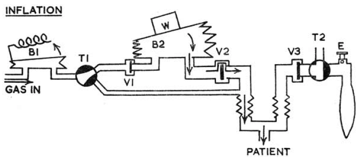
Wouldn't it be cool if we had some sort of switch that allowed the anaesthetist to choose between mandatory ventilation, and some other breathing system, such as - oh I don't know - a Mapleson D circuit?
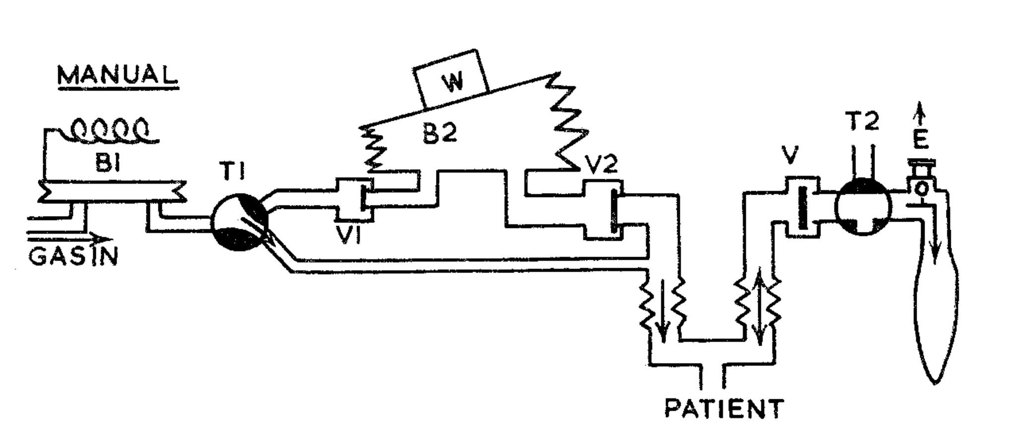
Just look at that beauty, drawn by Manley himself in his original paper.
A simple tap switch (T1) converts the whole system into a Mapleson D.
The second tap switch (T2) then allows you to let the patient breathe entirely by themselves, or connects them to the bag for manual ventilation.
Utter brilliance.
In summary
Hopefully the inane ramblings above have made even a modicum of sense, and as a result the key features of the Manley MP3 ventilator that you need to know for the exams are actually understandable, rather than something to be memorised.
Tell me the key features of the Manley MP3 ventilator
The main selling point of the new examination format seems to be an increased relevance to our day to day practice, so if this comes up in your CASE examination then I can only offer you my sincerest condolences.
Unless you happen to have read this post just before hand, in which case you're welcome.
Hopefully these features now make a bit more sense, rather than just being words to memorise.
- Pneumatic powered
- Pneumatic controlled
- Time cycled
- Minute volume divider
- Mapleson D for spontaneous breathing
And here's the official schematic
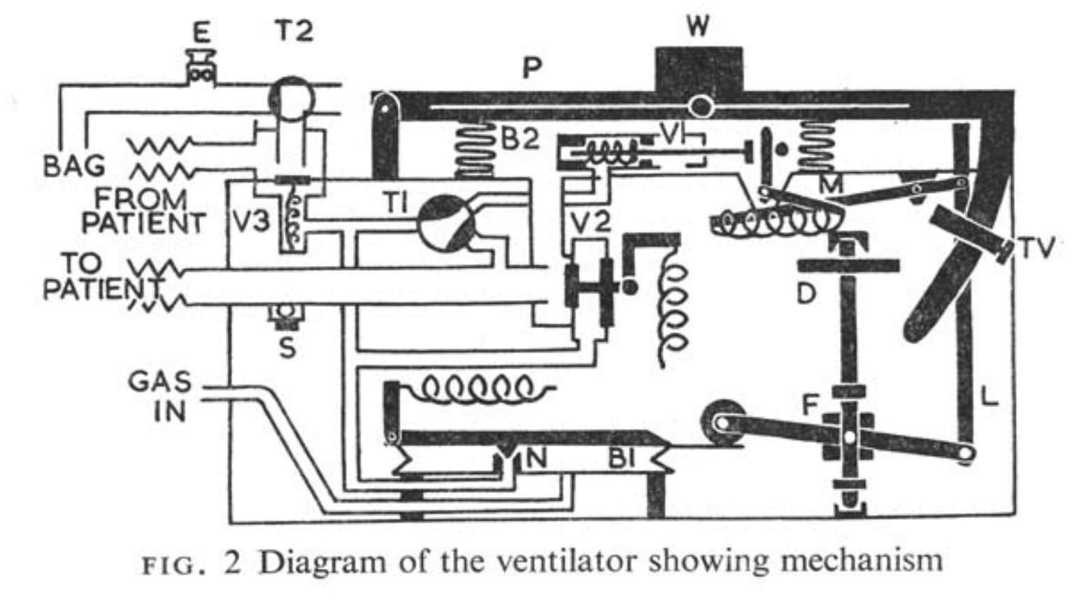
See if you can match our description to this diagram.
References and Further Reading



Other ventilation posts
 Anaestheasier ltd.
 Anaestheasier ltd.
 Anaestheasier ltd.
 Anaestheasier ltd.
Just a quick reminder that all information posted on Anaestheasier.com is for educational purposes only aimed at trained professionals, and it does not constitute medical or clinical advice.
Anaestheasier should not be used as a definitive resource for academic writing, please reference original source material.
Anaestheasier® is a registered trademark.